I recently bought a X-Ring WS2812B RGB on AliExpress.com. There is no information about the wiring or the bus how the X-Ring is controlled. So I did a little reverse engineering and want to share the information:
At first: the X-Ring is driven by a One-Wire connection.
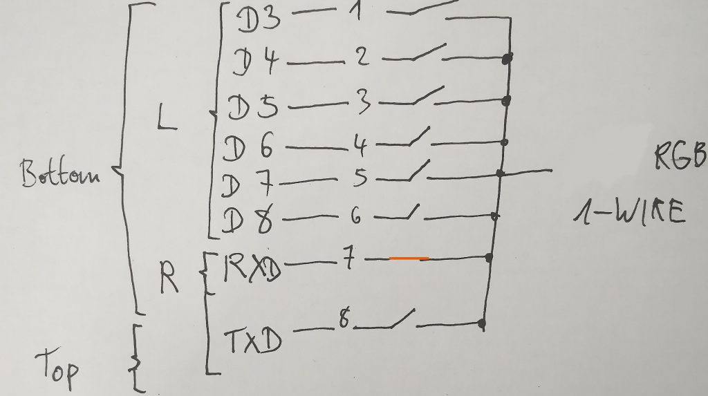
There is a switch on the top:
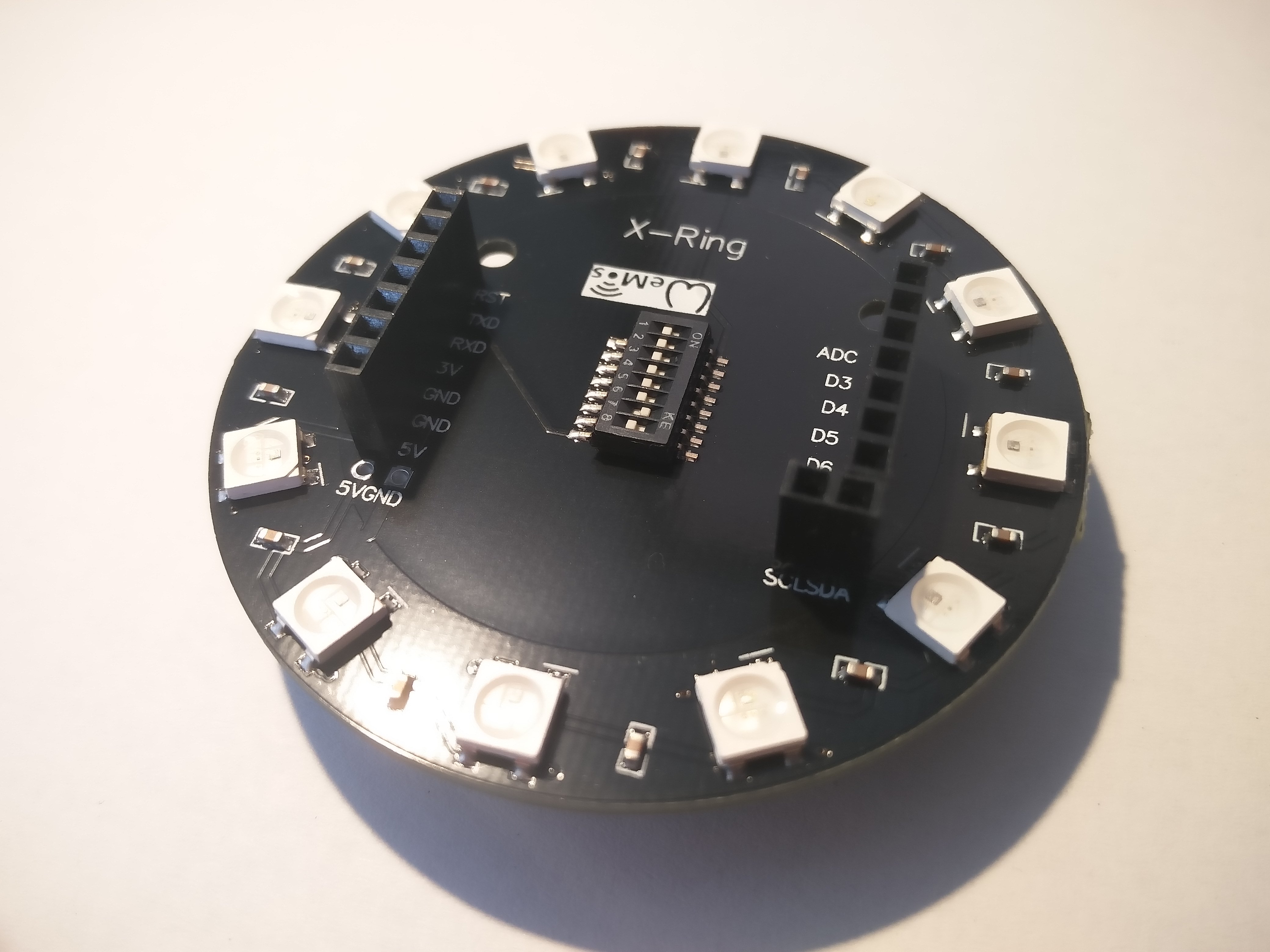
The wiring is the following:

When I ordered they had “ESP8266, Wemos d1 mini” in the title. The board also has a Wemos-Logo on it. But it is not compatible to Wemos D1 mini. The widths do not match!
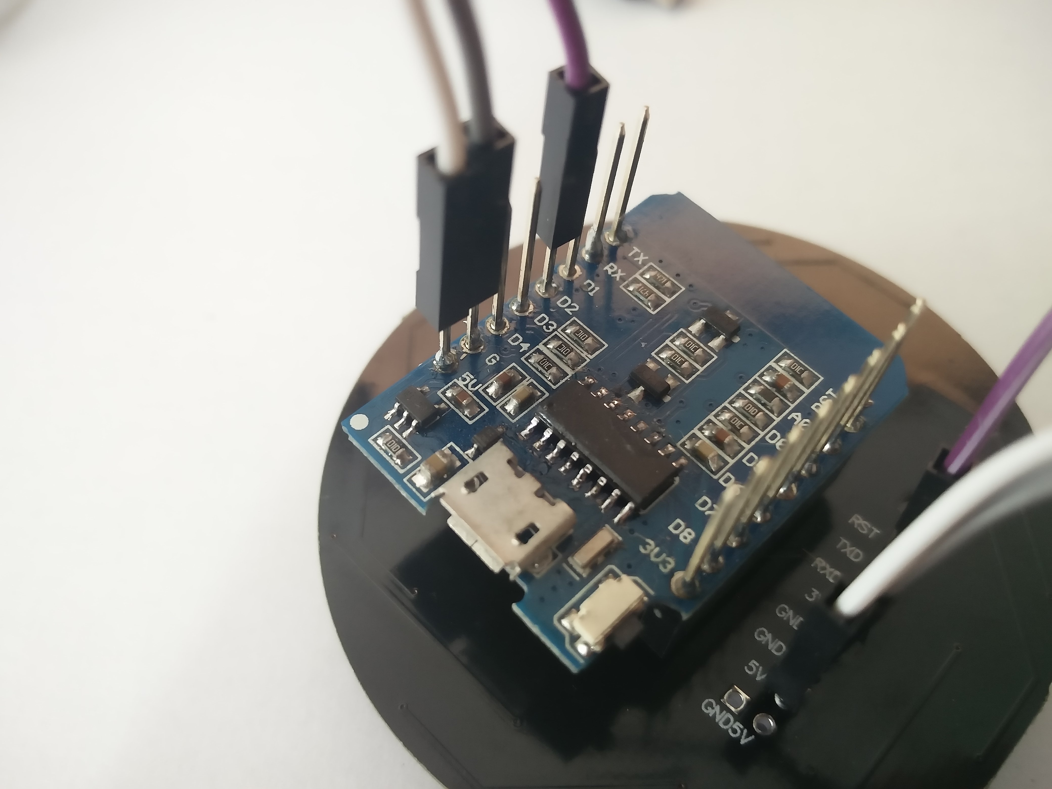
But you can easily mount an Wemos D1 mini to the board. I decided to connect the wemos to the bottom left side because then you can connect the Wemos D1 mini easily with wires to the board (5V, GND). You can choose to connect the Wemos D1 mini to RXD or TXD then (doesn’t matter as long you switch the according pin on the DIP-switch). Basically all labels on the board are irrelevant for an Wemos D1 mini (except: 5V, GND) because it is not compatible.
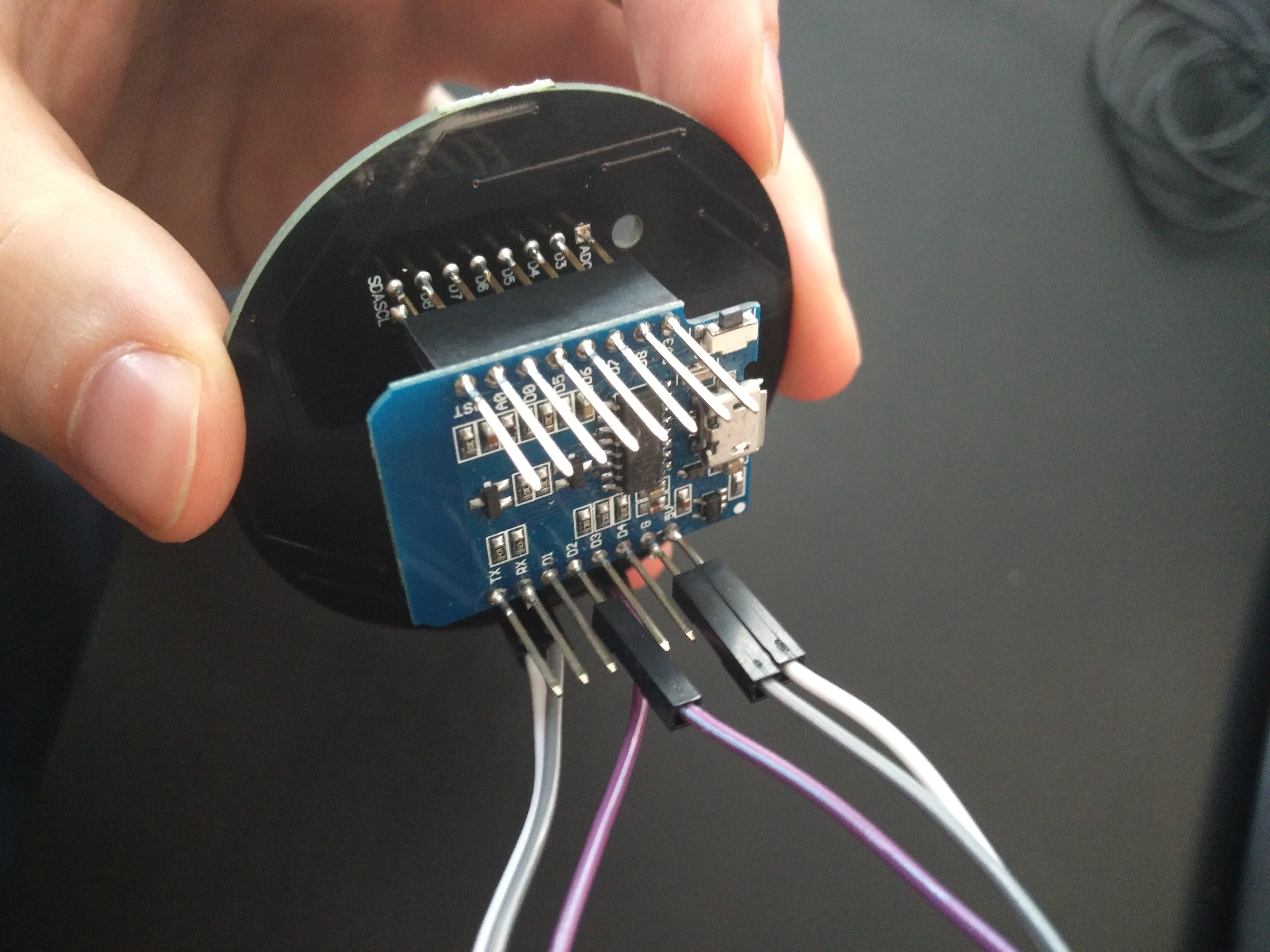
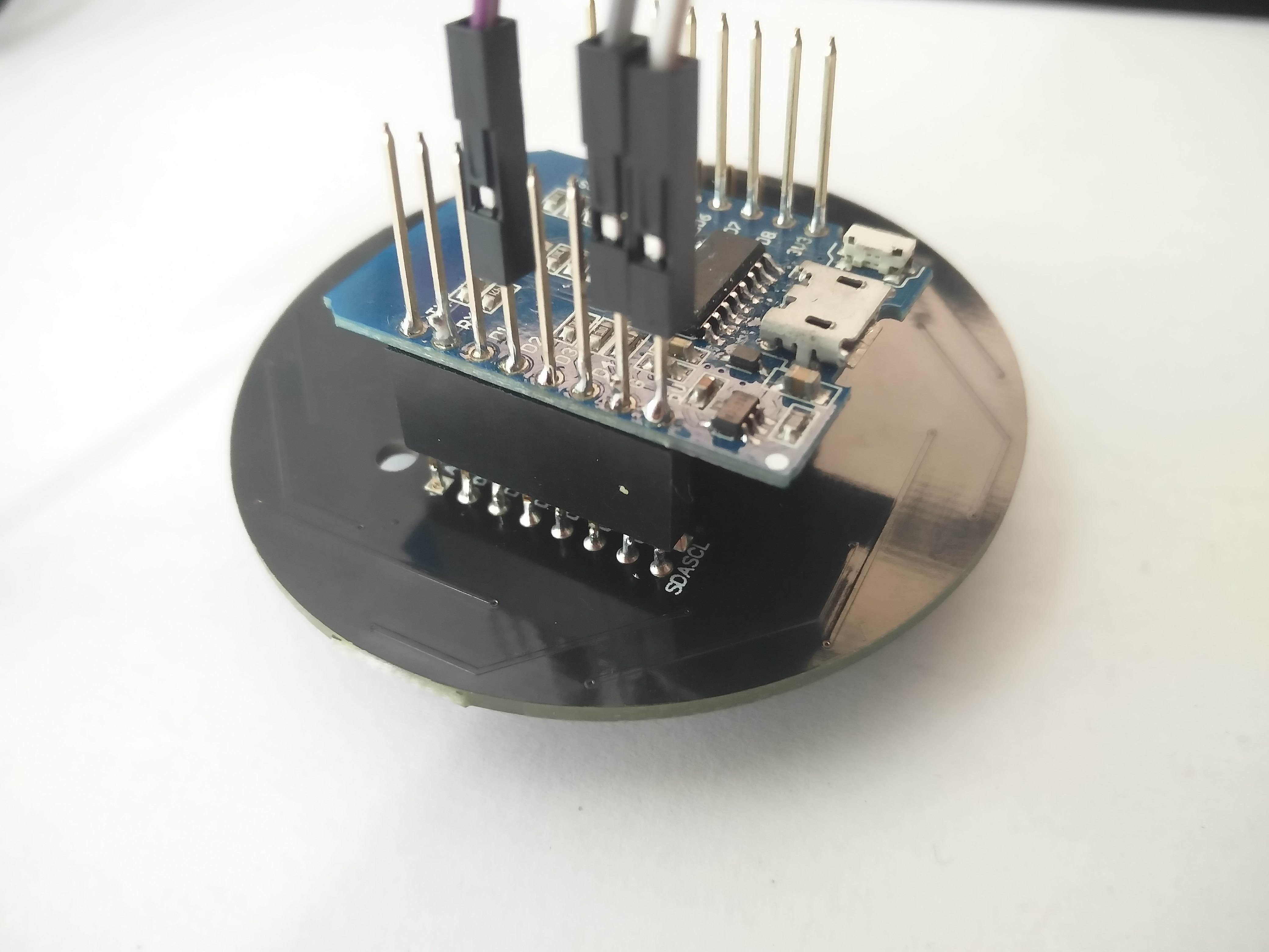
The wiring on the pictures is as follows (how to read: on the left hand side the pin name on the ESP, right hand side the X-Ring):
GND->GND
5V->5V
D2->RXD(7)
Make sure to switch the pin “7” on the DIP-switch, located on the top of the X-Ring, to the right as shown in the images. This acts as a pin selector and effectively connects the One-Wire with the RXD(7) pin. Make sure to switch at most one pin to the right.
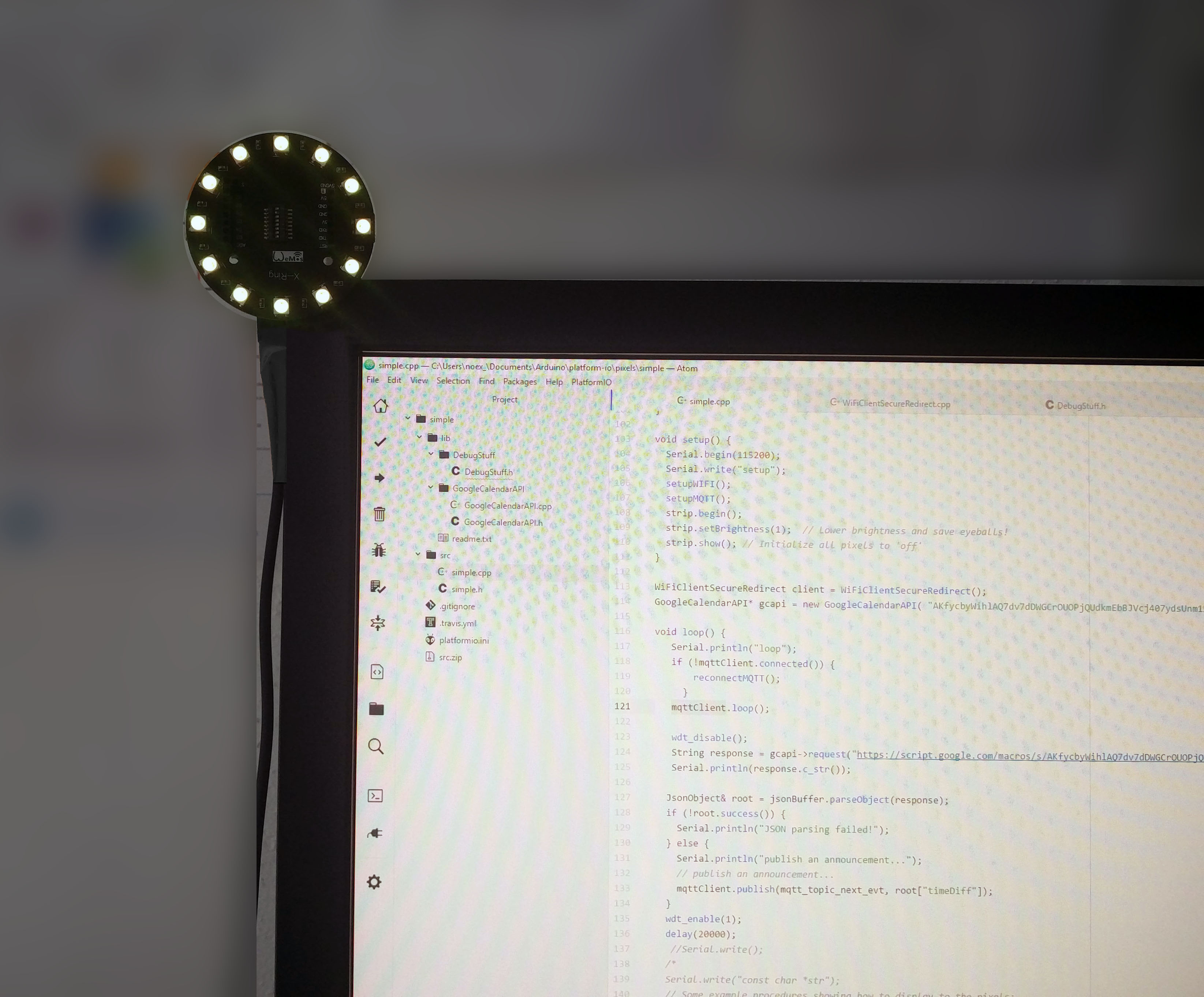
Then you can start programming the X-Ring
#include <Adafruit_NeoPixel.h> // https://github.com/adafruit/Adafruit_NeoPixel

#define PIN D2
#define STRIPSIZE 12

// Parameter 1 = number of pixels in strip
// Parameter 2 = pin number (most are valid)
// Parameter 3 = pixel type flags, add together as needed:
//   NEO_KHZ800  800 KHz bitstream (most NeoPixel products w/WS2812 LEDs)
//   NEO_KHZ400  400 KHz (classic 'v1' (not v2) FLORA pixels, WS2811 drivers)
//   NEO_GRB     Pixels are wired for GRB bitstream (most NeoPixel products)
//   NEO_RGB     Pixels are wired for RGB bitstream (v1 FLORA pixels, not v2)
Adafruit_NeoPixel strip = Adafruit_NeoPixel(STRIPSIZE, PIN, NEO_GRB + NEO_KHZ800);

void setup() {
  strip.begin();
  strip.setBrightness(25);  // Lower brightness and save eyeballs!
  strip.show(); // Initialize all pixels to 'off'
}

void loop() {
  // for each pixel set color to red. Wait 100ms between each individual pixel.
  for(uint16_t i=0; i<strip.numPixels(); i++) {
      strip.setPixelColor(i, strip.Color(64, 0, 0));
      strip.show();
      delay(100);
  }
}
Hello, I’ve just purchased an X-ring in Aliexpress with an ESP32. Unfortunately the ESP32 has broken so I will use it for the time being with an ESP8266 Lolin. Could you please show some code on how to use the X-Ring? I guess I need to program the X-Ring with one cable and connect it to a ESP8266 pin (plus GND and 5v). Do I need to mess with the microswitches on the X-Ring?
Thanks a lot and best regards / Fernando
Hi Fernando,
you need 3 Wires: Of course connect GND, 5V according to my pictures. You have to choose a pin for the 1-Wire signal (please look carefully to the pin illustration I have made). In my case I have enabled pin 7 on the switch – that’s the RXD labeled pin on the X-Ring board. On the ESP I chose D2. The code is really simple due the Adafruit_NeoPixel library. I have added a simple example to the post that should run out of the box if you follow the wiring on my pictures.
If you want to have the correct board pinout
ESP8266 ($5)
https://www.banggood.com/fr/Wemos-X-8266-ESP-WROOM-02-Development-Board-D1-Mini-Nodemcu-WiFi-Internet-Of-Things-ESP8266-Module-p-1176178.html
ESP32 ($10)
https://www.banggood.com/fr/Wemos-Lolin-ESP32-WiFi-Module-Bluetooth-Dual-ESP-32-ESP-32S-ESP8266-p-1148418.html
Little more expensive than other, but painless 😉
Thanks for the hint!
Hi,
I’ve just wanted to thank you for your amazing write-up.
Thanks to you I had my x-ring running in no time.
Again Thank you very much.
Hi Michal, thanks for your feedback! I’m really happy that it actually helps somebody. What are you going to develop with the X-Ring?
Hi,
great info!!
But on my x-ring, I only get one LED to change color following your setup.
All the other LEDS are bright white.
Any ideas whats wrong?
Hi Bjorn, Miachel reported that the information helped him to setup the X-Ring and mine is working fine too. I can’t tell you what’s wrong. But if you get one LED to red the wiring should work. Maybe your X-Ring is broken and the LED after the first one are not connected to the bus properly. Please check the soldering to identify loose junctions.
hello
my xring is working god because of your tutorial, thank you
now i want to do something different. i have a ledstrip that is controlled from a wemos d1 mini with relay shield. code in link
https://github.com/Innovativetom/InnovativeTomDemo-Wemos-Relay
now i want to do the same with the x ring and change the color from it all from my phone.
in the app i use (see second link) you set up twoo buttons, one for ON and one for OFF. in each button you place an url so if you would press the button it sends a signal to that url. the wemos board then know that he needs to swithc the relay. now i want to do the same thing with the xring but without a relay because the xring can be powered through the board.
link 2 https://itunes.apple.com/us/app/curler-your-http-apis-interface/id1210896283?mt=8
i hope you can help me.
greets from belgium, Amaury
Hi amaury,
since you use a wemos d1 mini you should be able to implement this really straightforward. I recommend you setup a http server on the wemos and distinguish the HTTP requests for ON and OFF. You can start from the examples like https://github.com/esp8266/Arduino/tree/master/libraries/ESP8266WiFi/examples/WiFiWebServer
Hey Man great info… saved me a lot of time. Do you have any idea of the power requirements of this XRing ?
Hi Martin, it’s just a WS2812B LED strip with max 0,06 A per segment ( the current dependents on color and brightness of course ). So max 0,72 A.
Hi. Can I connect one esp8266 to two XRings?
I want to make a lamp with 2 xrings – on the bottom and top. I want those xrings to simultanously, displaying same effect. Is it possible?
Yes, this should be possible. You can use the signal (e.g. on D2) to drive both X-Rings.
thank you!
But i lost about 30 mins on how to make it work. You didn’t mentioned that we have to switch this “miniswitch” no 7 to on 🙂
it is important for some rookies like me 😀
thanks
Oh sorry! I have updated the content. In my opinion it was sufficient to mention the DIP switches and an image of it.
Hi, Your very great. Its functioning immediately. Thankyou very much. Greez from Vienna, Austria